How does the EMC Filter work?
- June 10 2018
- Commercial Announcement
- 1690 Reads
- 0 Comments

Interference Sources
Typical sources of interference are, for example, IGBT inverters for motor control and switched power supplies. Both devices generate voltages and currents with steep edges in their operation. The interference spectrum covers the entire range of 0.15 to 30MHz where the conducted emissions is measured and 30 to 1000MHz where radiated emission is measured.
Differential (Symmetrical) Interference ModeFor low frequencies, in hundreds of kHz, the interference is spread the same way as the power supply voltage. Current flows in the loop formed by the L and N conductors.
Common (Asymmetrical) Interference Mode
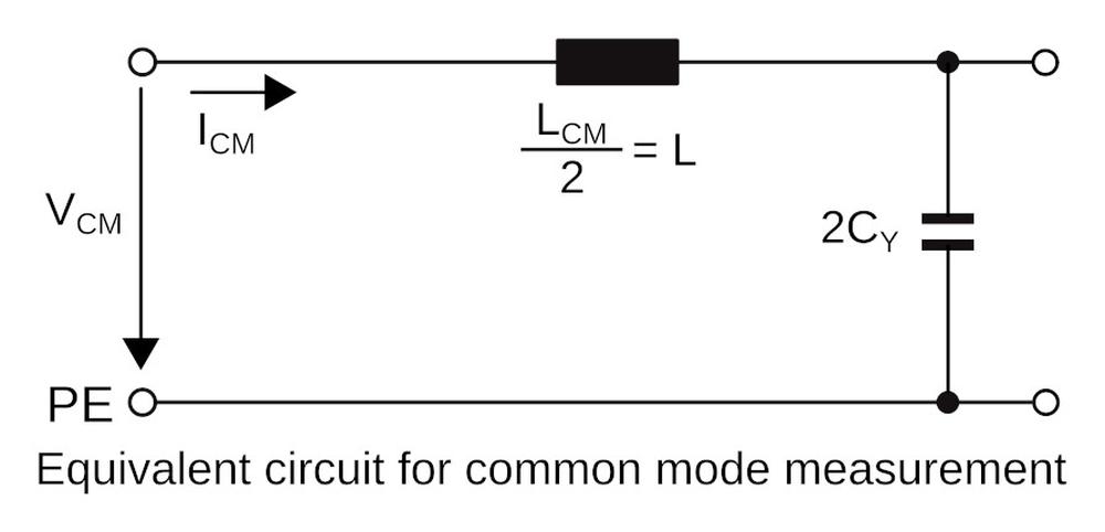
For higher frequencies, above 1MHz, the parasitic capacities in the source of interference and the disturbed equipment also produce an interference current in the earth circuit. This common-mode interference current flows towards the disturbed equipment along both connecting lines and returns to the interference source through earth.

Typical EMC Filter

Common Mode Choke
Common mode choke has two windings on the same core. Coupling coefficient between L1 and L2 is k=M/(L1*L2)^0,5, where M is the mutual inductance between L1 and L2. In ideal case, L1=L2 and k=L/M
During normal operation and in differential interference mode magnetic flux generated by current through L1 is compensated by current flowing through L2 in the opposite direction. In this case, L1=L2=0.5*LDM=L-M. For typical toroid common mode choke M approaches to L and LDM~1%L
In common interference mode currents flow through L1 and L2 in the same direction, L1=L2=LCM=L+M
Filter Insertion Loss measurement
The insertion loss is a measure of the efficiency of filter. The test procedure used to measure insertion loss was updated in the IEC publication CISPR 17 in 2011 and was published as the EN 55017 standard. Generator output impedance Z0 and filter load Z2 is 50 Ohm.


Filter insertion loss depends on output impedance of interference source and load impedance. In the practice, interference source output impedance is not known and filter load impedance is not 50 Ohm. Therefore, the insertion loss graphs published in the datasheet can only be used to compare the filters to each other. It is not possible to estimate the filter attenuation in the real situation by using these graphs.

In order to better characterize attenuation in the differential interference mode, IEC CISPR 17 proposes to measure a filter with an interference source impedance of 0.1Ohm and a load impedance of 100Ohm and vice versa. This method of measurement approximates the worst case.

It is clear from the FMAB NEO 5500.2637.01 insertion loss graph that the differential mode interference suppression may be in the worst case 20 to 30 dB lower. The graph also shows that for the frequency range 20 to 50 kHz, the attenuation is negative. If some harmonic component disturbance falls into this band, it will not be suppressed but amplified!
Conclusion
For the estimation of attenuation for frequencies up to 1MHz (differential mode), it is advisable to consider 0.1/100 Ohm graph. Above the 1MHz frequency, the common mode interference prevails and the 50 Ohm graph approximates the actual EMC filter loss.
For further information about Schurter, products, please do not hesitate to contact us at schurter@soselectronic.com
Schurter EMC products:
- 1-phase and 3-phase EMC filters with different kind of connection ? quick connect terminals, bolts, screw clamps, PCB pins and wire leads
- 1, 2 and 3-stage EMC filters
- Medical EMC filters
- EMC filters integrated with IEC C8, C14, C18 or CEE inlet optionally also with switch and fuse
- Common mode chokes, SPICE model library


