

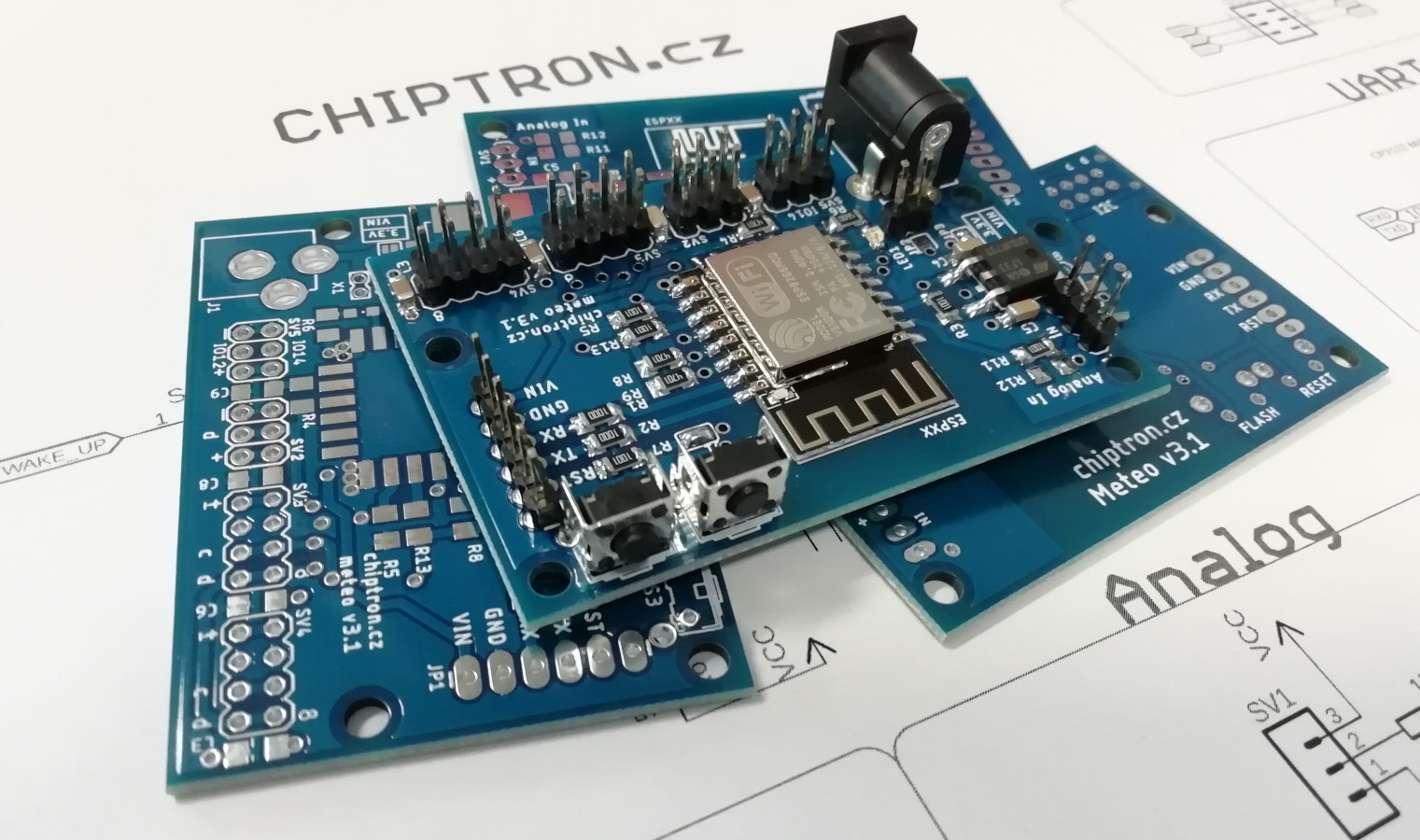
Meteo v3 - verstatile board with ESP12E/ESP07/ESP08
- March 30 2019
- ESP32, ESP8266, NodeMCU, Wemos ...
- 25548 Reads
- 0 Comments
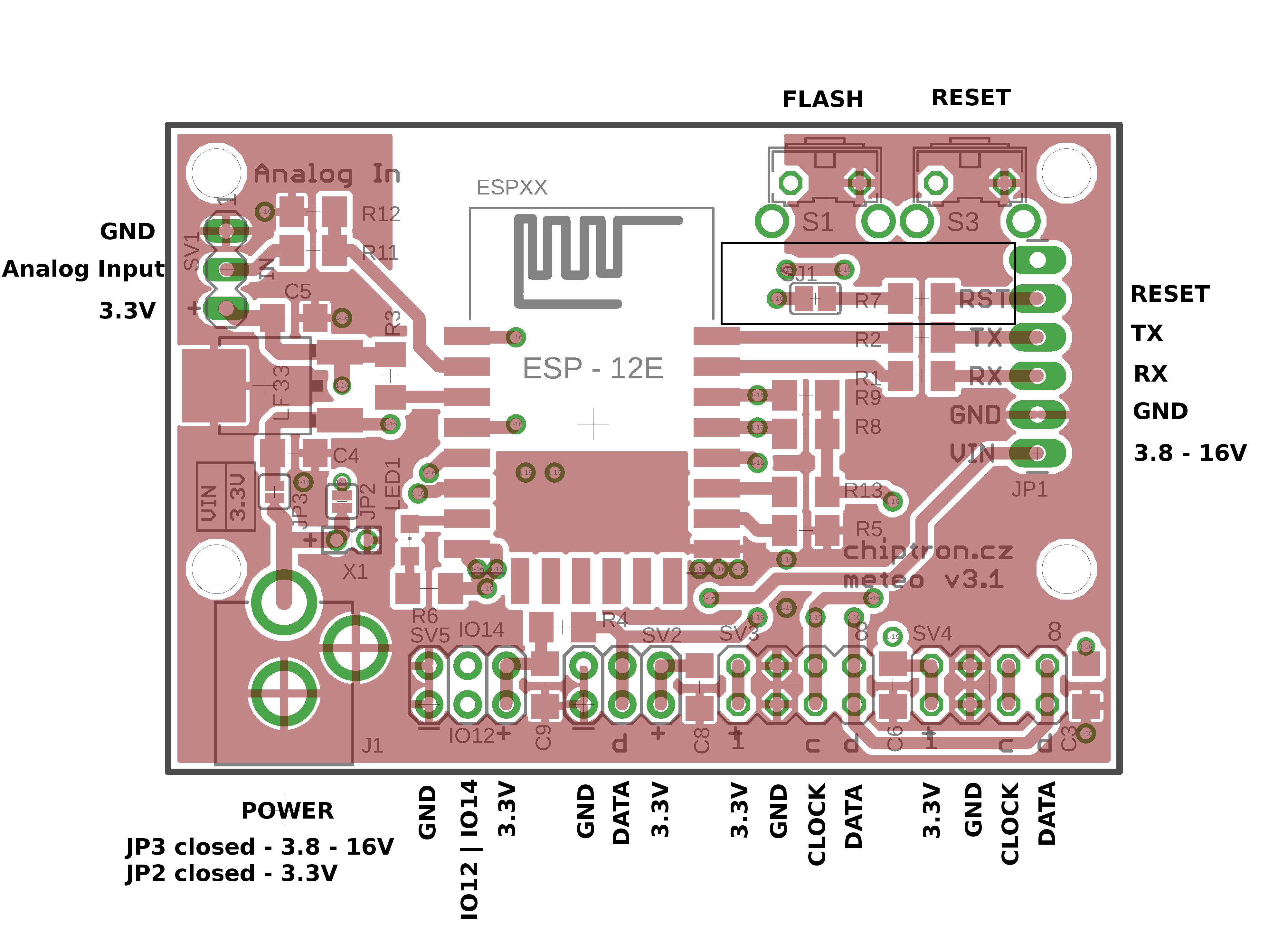
Meteo v3 is the latest version of board and you can easily connect I2C devices (sensors, ADC, DAC, LCD), 1-wire sensors and control output devices with 2 GPIOs which are connected to female header.
The PCB of this versatile board with ESP8266 you can buy on https://www.tindie.com/products/chiptron/meteo-v31-bare-pcb/
The documentation and example codes are available on https://github.com/petus/Meteo-v3-ESP8266
Key specs of Meteo v3
*Differences from Meteo v2
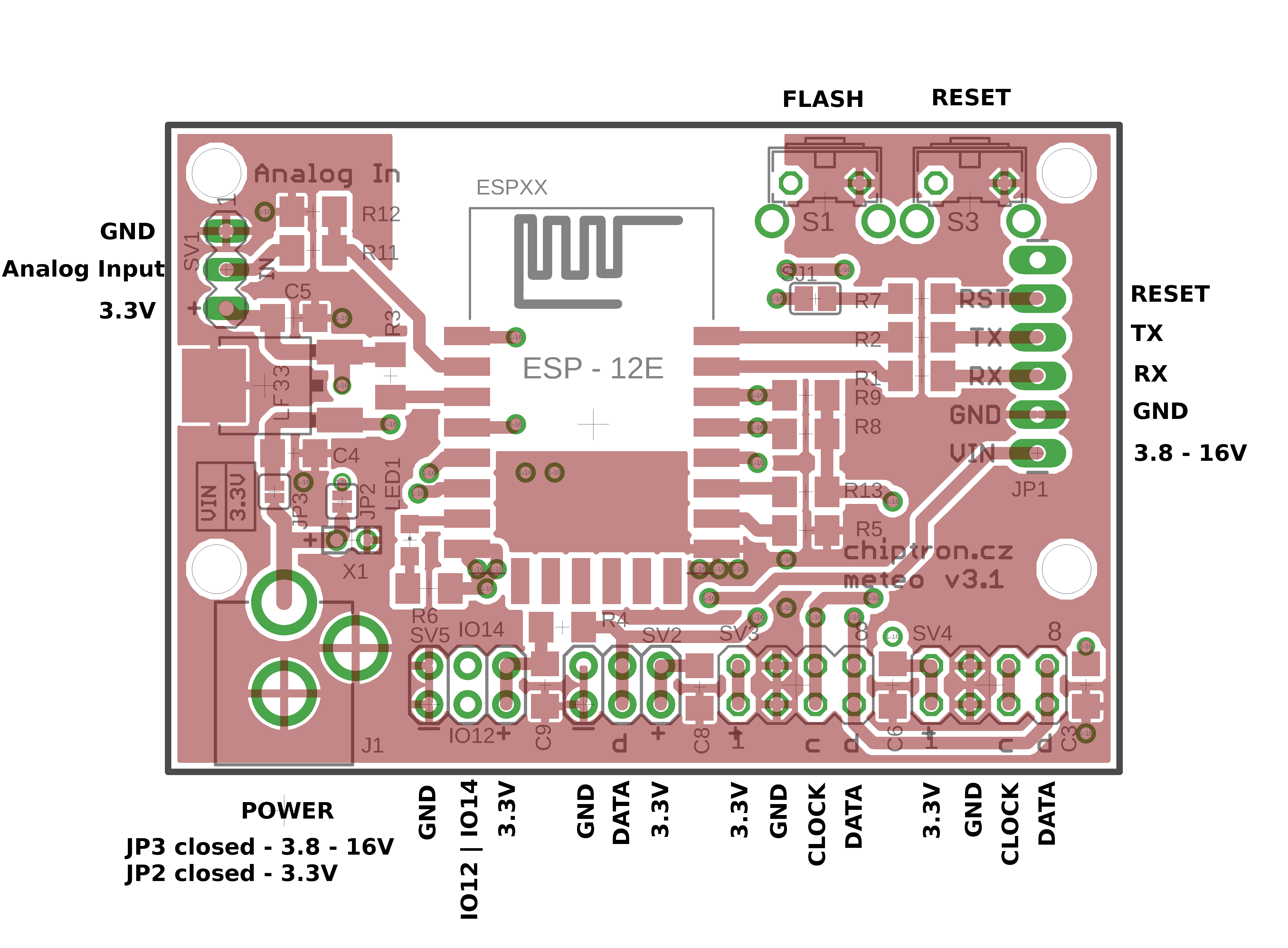
Power supply 3.8 to 16V - LF33 LDO
WiFi module with ESP8266 - ESP12E, ESP07 a ESP08
4x 4 female pins for connection of I2C devices (sensors, LCD, ...)
Analog input with resistors devider (maximum input voltage is 0 - 1000 mV)
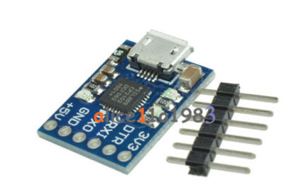
Programming with USB-UART converter
* Added 2x3 female pin for 1-wire bus with external pull-up for Data
* Added 2x3 female pin header for two GPIOs - GPIO12 (IO12) and GPIO14 (IO14)
* Modified pinout of UART programming connector, you is directly compatible with wit hthis USB-UART converter
* Modified pinout of I2C female heaeders, directly compatible with these sensors
* Power supply is DC-DC connector instead of microUSB
* You can choose power voltage with two solder bridges - 3.3V or you can use LDO and then the voltage is 3.8 až 16V
* Added 2 pin header for connection of other devices or shields or input of power source
This project Meteo v3 is not only board used for thermometer. There is a lot of improvements (DC-DC connector for power, 1-wire bus, GPIOs) may be used for more projects, just what you need.
The power may be 3.3V (JP2 solder bridge) or 3.8 - 16V when you close JP3.
If you want to upload the code to board, unplug DC-DC connector!
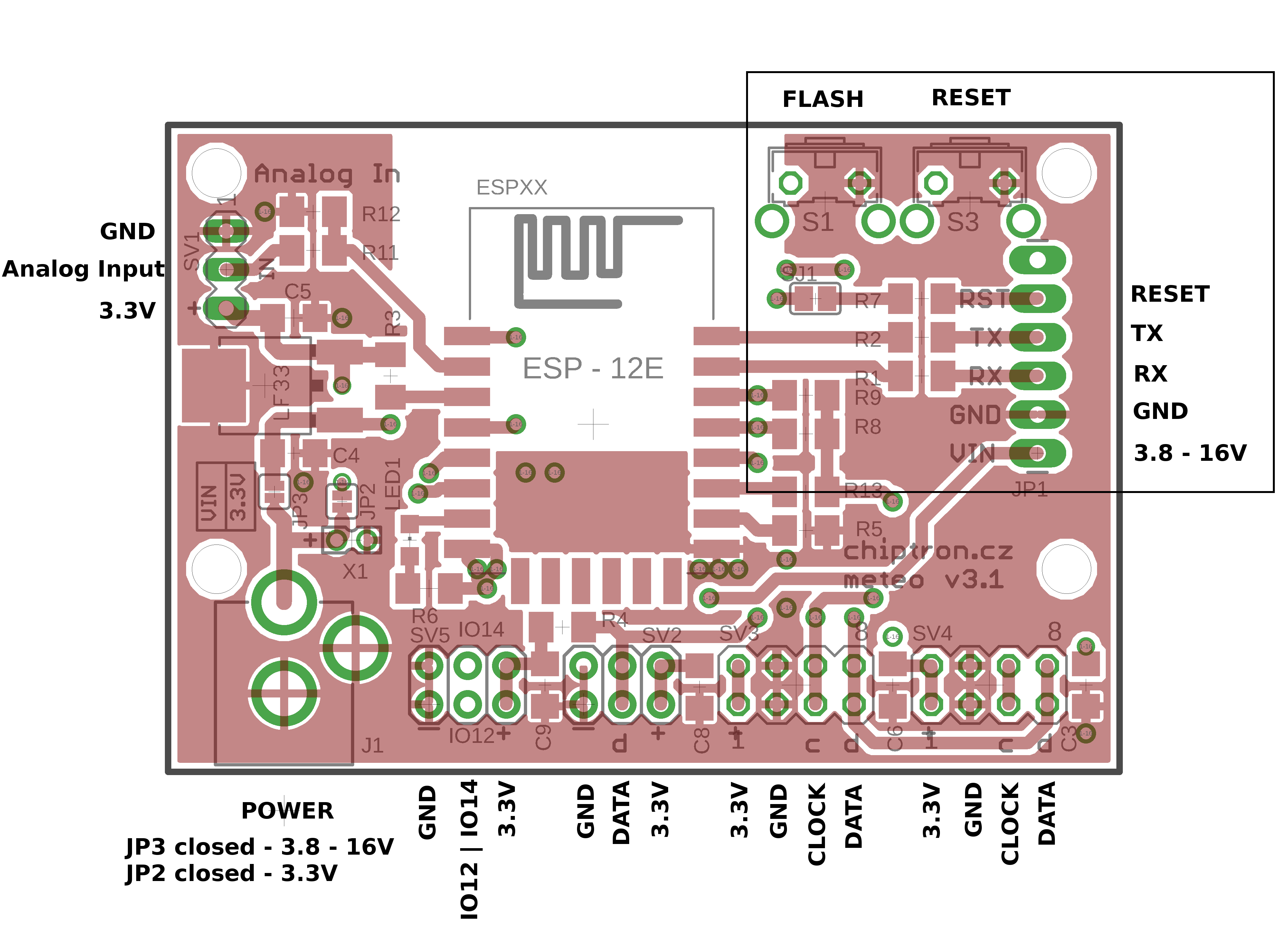
The connector for connection of USB-UART converter was modified and added by 5V power supply. The programming connector is compatible with this module.
The board is powered from 5V output of USB-UART converter.
If you want to upload the code to board, unplug DC-DC connector!
The board now includes 2x3 female header for connection of devices with 1-wire bus. External resistor (4k7) is connected to DATA which is connected to GPIO0 of ESP8266.
The pinout of I2C bus was modified and now is directly compatible with these sensors. If you want to use different sensor, just change the connection.
Programming of Meteo v3
If you are using Arduino IDE, you can easily upload your code to board - at first, add link to Manager in Preferences.
To File -> Preferences -> Manager others URLs paste this link
http://arduino.esp8266.com/stable/package_esp8266com_index.json
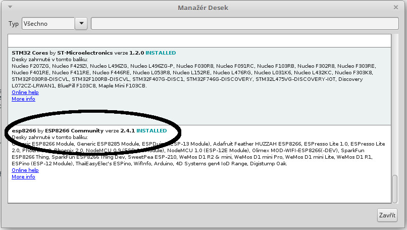
Then, open Board Manager and install the ESP8266
Tools -> Board -> Board Manager and write ESP8266 to search box
At the end, choose NodeMCU in Tools -> Board
If you want to upload your code, unplug DC-DC connector!
Connect the USB-UART converter:
5V - 3.8 - 16V
GND - GND
RX - TX
TX - RX
DTR - RESET
For programming in Arduino IDE or others tools, press the FLASH button before the uploading. Then you enabling of uploading.
You can release the FLASH button after the message "Uploading" in terminal (of Arduino IDE).
Instead of pressing of FLASH button, you can close DATA of 1-wire bus with GND. After the upload, remove the jumper.
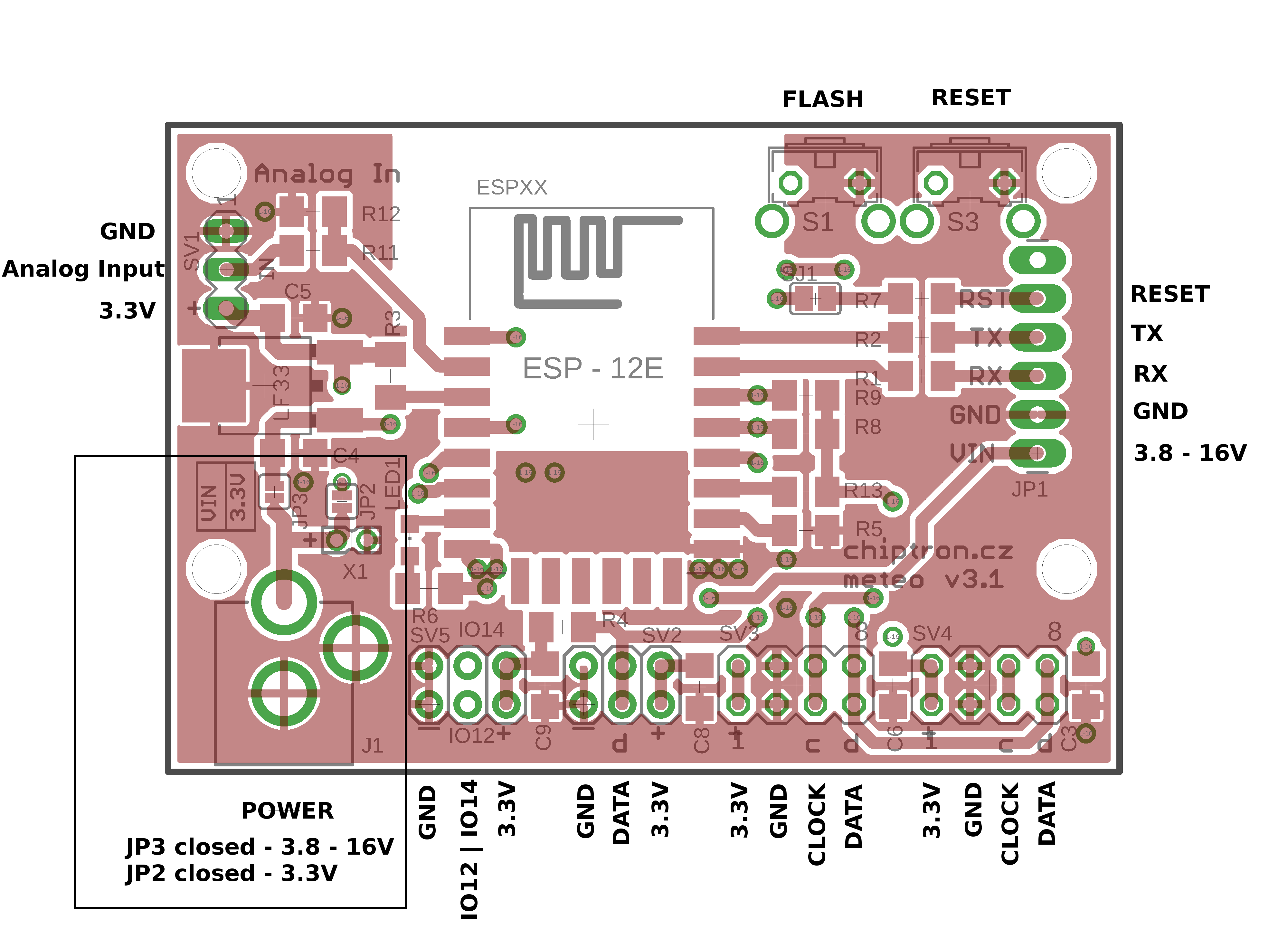
Powering of Meteo v3
The powering of board can be done by 5V output of USB-UART connector or DC-DC connector. Be careful, if you want to connect USB-UART, uplug the DC-DC connector.
The input voltage from DC-DC connector you choose by soldering of bridge (JP2, JP3).
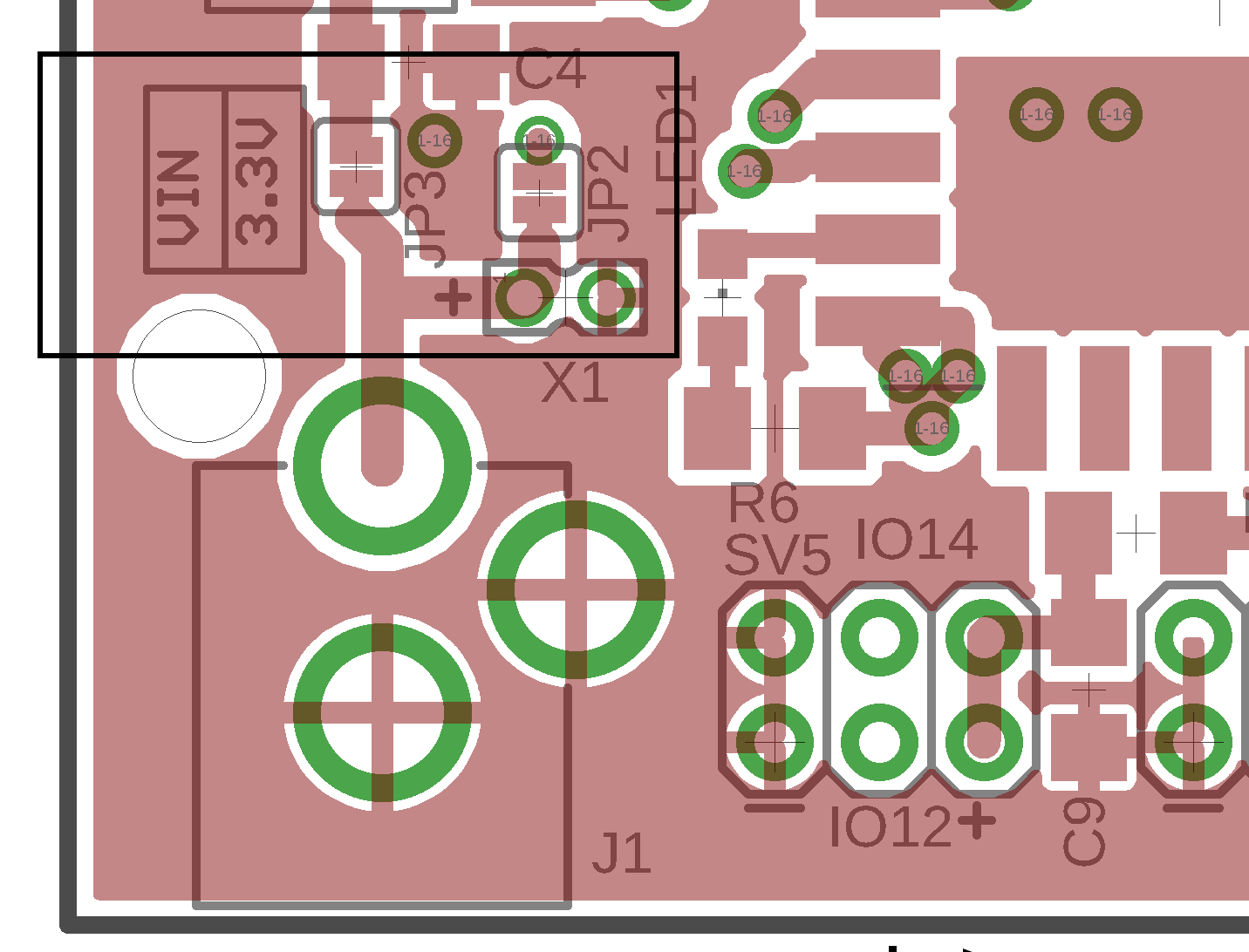
If you short JP2, maximum voltage is 3.6V, recommended 3.3V.
If you short JP3, the power voltage may be from 3.8V to 16V.
The minimum voltage is based on minumum power voltage of ESP8266 plus 0.5V (drop on LDO), it means the minimum voltage is 3.8V.
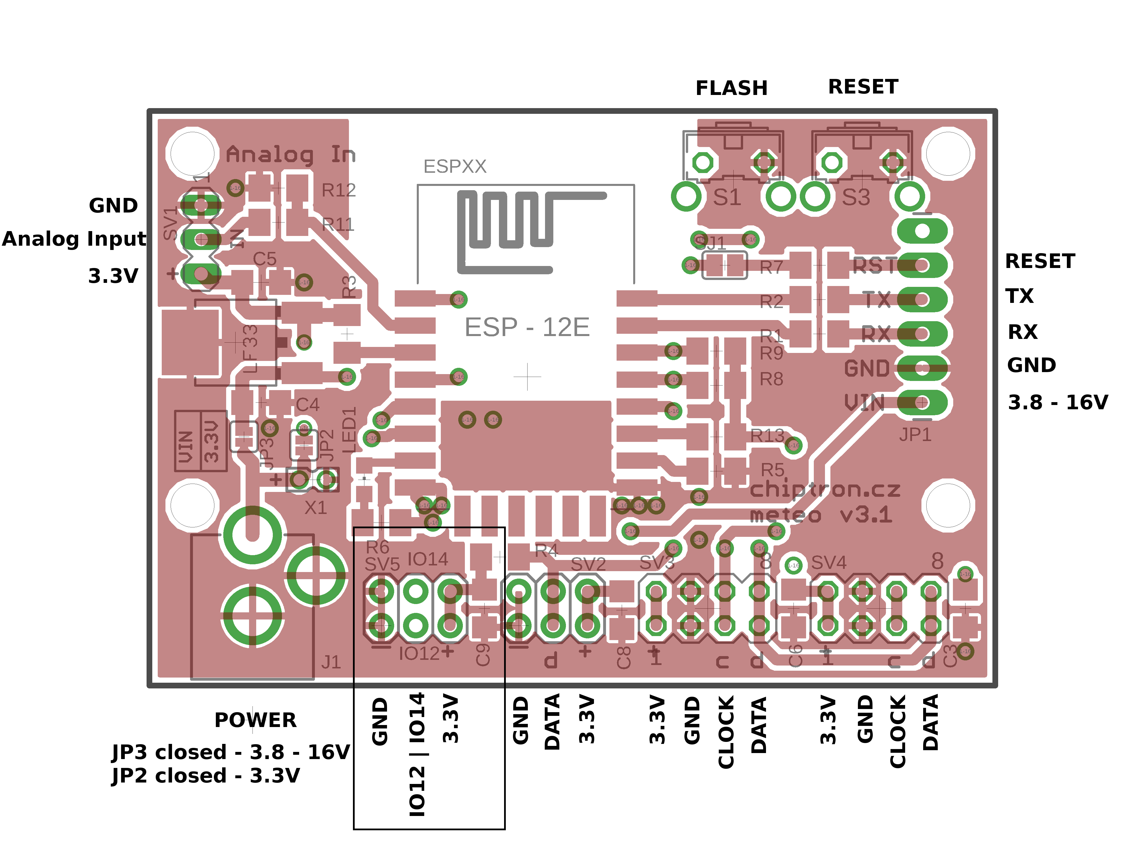
Input/output - GPIO
A new revision of board includes two GPIOs. They are labeled like IO12 and IO14.
GPIOs are without protections so be careful with using of that. If you want to switch the relay, do that with transistor.
Both pins are with female pins of GND and 3.3V.
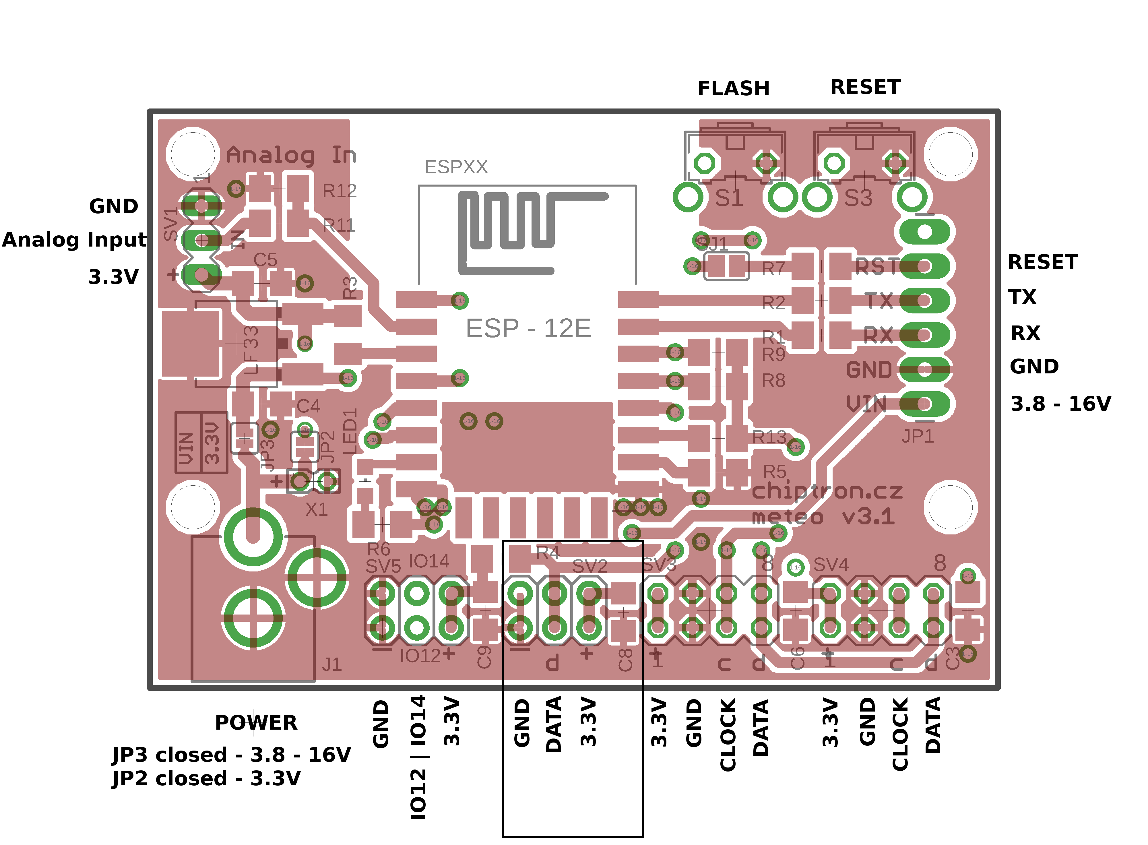
1-wire bus
The popularity of 1-wire is extremly high, the most popular sensor is DS18B20 - temperature sensor.
The sensor can be powered by two options - usual or parasite.
There is 4k7 resistor which is connected between DATA and 3.3V.
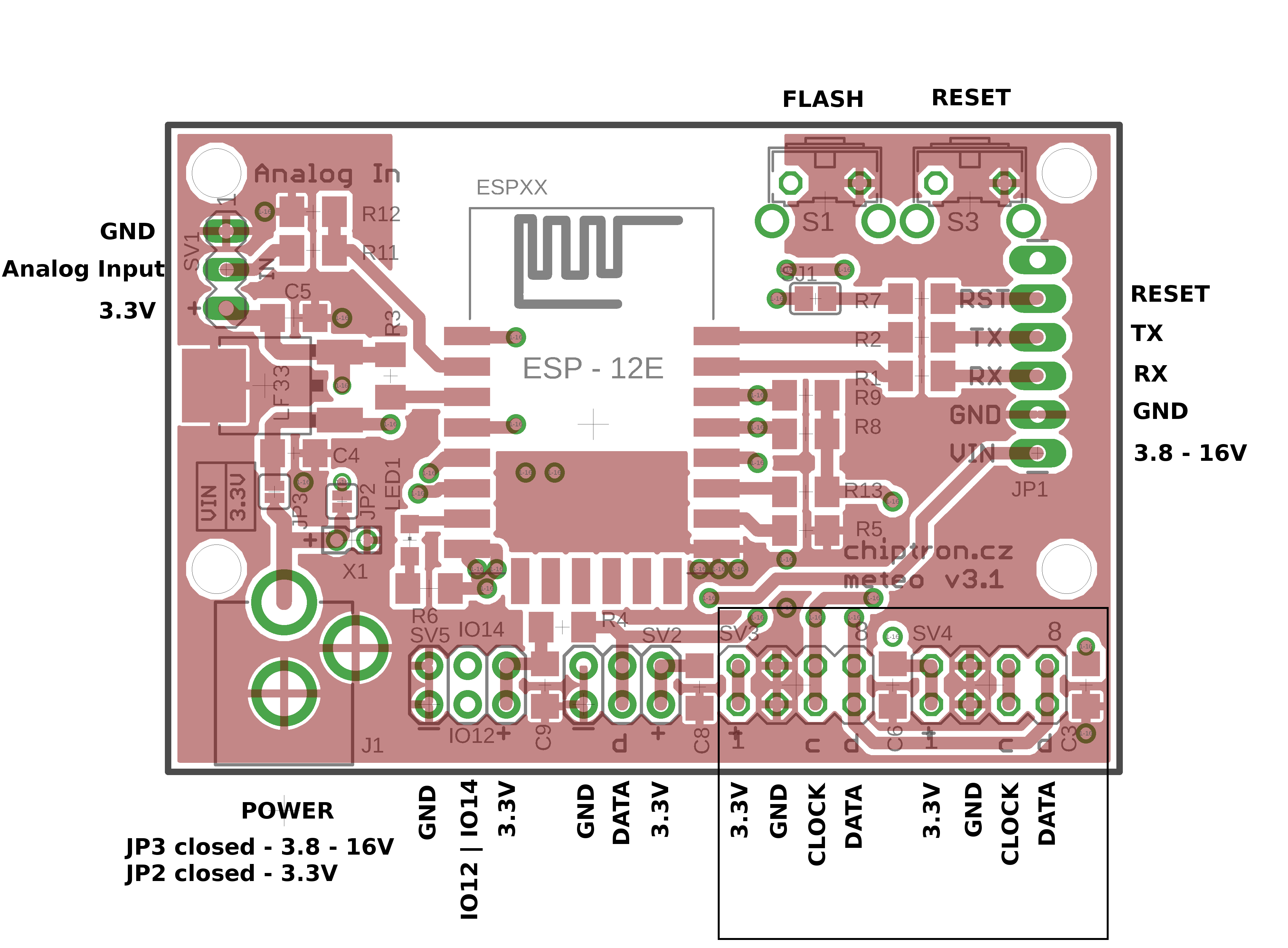
I2C bus
The connection of sensor and LCD is done by I2C connector. These connectors are four so you can connect a lot of I2C devices.
The maximum length of wires is limited by capacity of wires (400 pF).
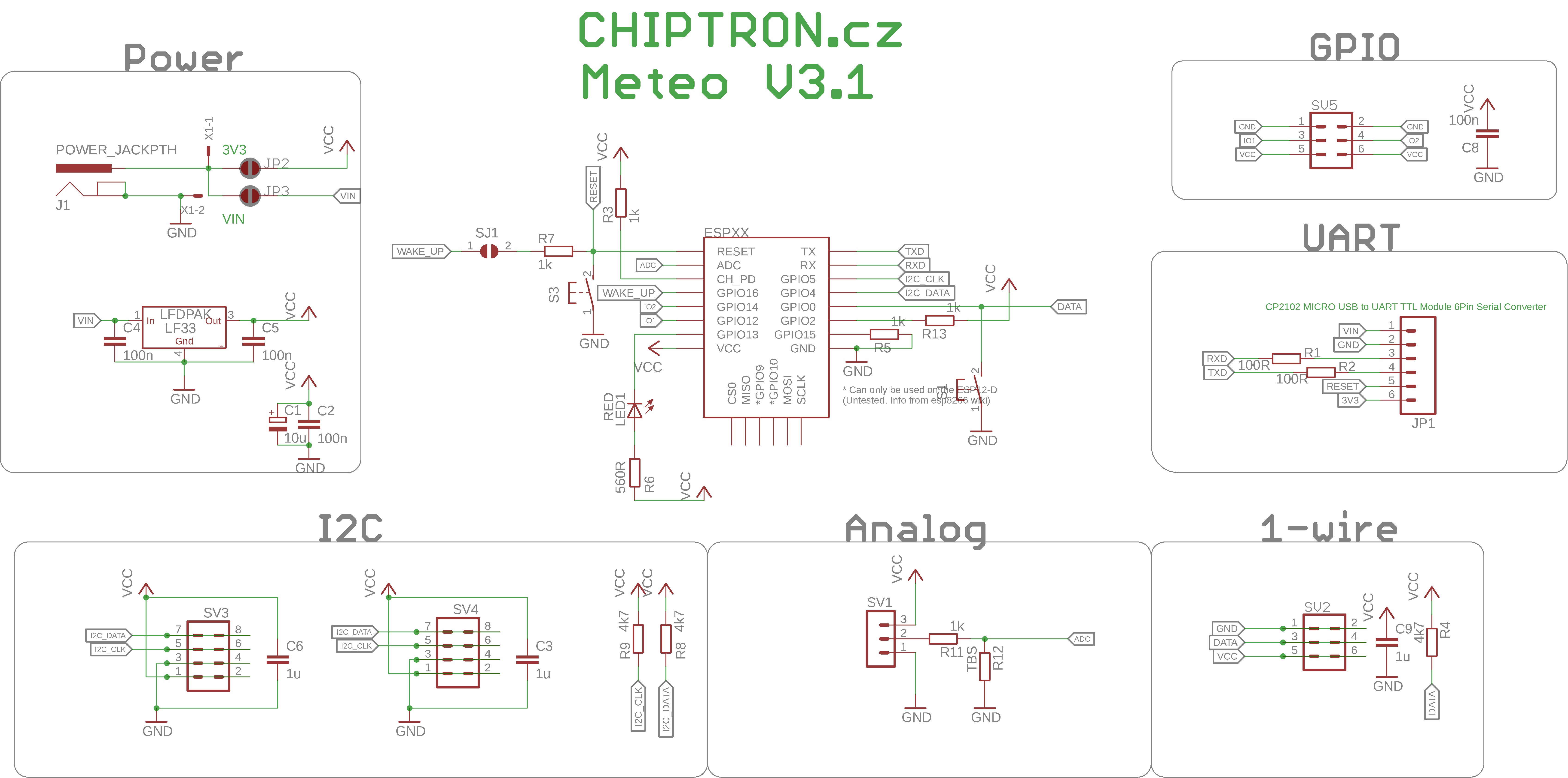
Clock and Data are connected to GPIO5 and GPIO4, there are designed pull-up resistors (R8 and R9) which you can assemble.
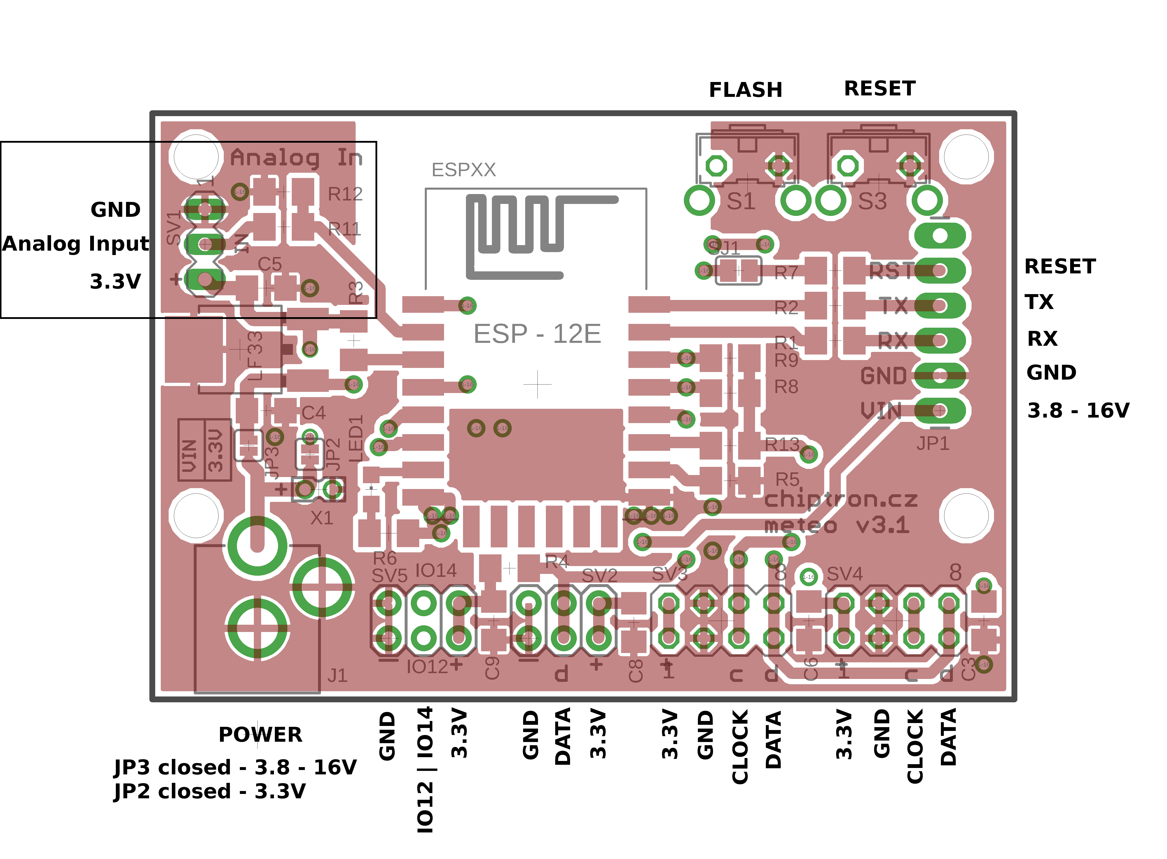
Analog input
ESP8266 contains only one ADC, the maximum voltage of analog input is 1000 mV.
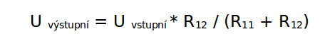
If you want to connect device with higher output voltage, you have to use prepared resistors divider.
Formula for calculation of voltage
If you need mote Analog inputs, you can use external I2C ADC, which you can connect to I2C connectors on board.
Low power consumption of ESP8266
In case you want to save energy from battery, you can use a few low power modes.
If you want to use DeepSleep, you have to short SJ1 - then you short GPIO16 and RESET and the ESP8266 is correctly restarted (after the timeout of DeepSleep).
Schematic
Schematic
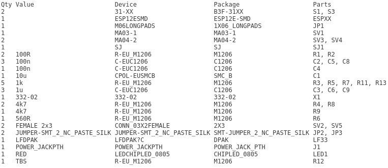
BOM:
Example codes
You can find a few examples on github - LED blinking, PIR sensor (connected to GPIO12), DS18B20 with 1-wire bus, I2C sensors (Si7021 and BMP180), OLED and more.
Don't hesitate and write your own codes and share it!
Power consumption from LiPol battery
During the testing of Meteo V3.1 I tried LiPol like power source of board.
The LiPol was connected through DC-DC connector. The capacity of battery was 850 mAh and the Meteo V3.1 measured temperature every 5 minutes and also sent value to webserver. The temperature sensor was DS18B20.
With this configuration the Meteo V3.1 worked 46 days, it means avarage power consumption was 770 uA.
The highest consumption during sleep mode had voltage regulator LF33 (typ. 500 uA).
The dependecy of quiescent current on input voltage of LF33.
4 V - 513 uA
6 V - 522 uA
8 V - 530 uA
10 V - 548 uA
12 V - 556 uA
14 V - 565 uA
16 V - 572 uA
If you choose the battery with nominal value max 3.6 V, you can skip the LF33 (close the JP2 solder bridge) and then you are able to achieve much longer lifetime of board. In this case three times.
The PCB of this versatile board with ESP8266 you can buy on https://www.tindie.com/products/chiptron/meteo-v31-bare-pcb/