

When do we need Analog Discovery, and when do we need Digital Discovery?
- November 03 2017
- Commercial Announcement
- 3017 Reads
- 0 Comments
Digital Discovery is a device similar to Analog Discovery in that both are compatible with WaveForms 2015 environment. However, Digital Discovery is only equipped with tools for operating on digital signals ? a logic analyser, a logic signal generator, and a protocol analyser. It is capable of testing a set state of inputs/outputs (static mode). It also enables digital signal sequencing with a script editor. It has a built-in power supply. The Digital Discovery offers more channels, faster sampling rate, and additional optimisation options to suit your needs.
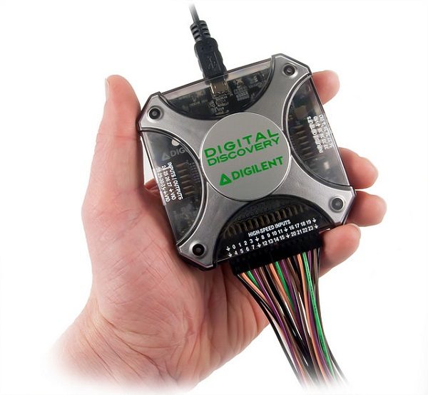
pic. 1. Portable Digital Discovery.
Logic analyser
Digital Discovery's logic analyser uses fast inputs, therefore with 32 channels it can reach a sampling rate of 200 MS/s, with 16 channels it increases to 400 MS/s, and with 8 channels it reaches 800 MS/s. That is two/four/eight times faster sampling rate than the rate offered by Analog Discovery 2, which only has half as many digital channels available!
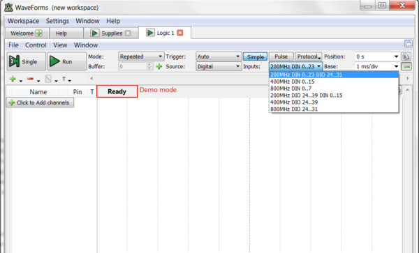
pic. 2. WaveForms software.
Digital Discovery's input and output channels
Digital Discovery's logic analyser has 24 digital channels defined as input channels. Another sixteen channels are digital output channels. In comparison, Analog Discovery 2 only has 16 digital channels, shared between its logic analyser and logic signal generator.
What's more, Digital Discovery's inputs and outputs are configurable to a certain extent. Namely, the power supply (other than supplying power) lets you configure the digital inputs' and outputs' specifications, adjusting them to the system being tested. You can:
? set the voltage level defining a high logic state and its active threshold (pick from five levels),
? set the current levels for each output or leave them on auto,
? change the output signal rise time.
The aforementioned features make Digital Discovery an excellent tool for embedded system development.
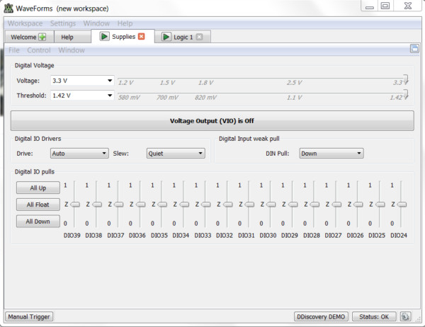
pic. 3 Digital Discovery's input/output configuration window of WaveForms software.
Example of Digital Discovery application
project goals
This project was created to demonstrate Digital Discovery's functionality, and its detailed description is available on Digilent's blog. A 48-pin FPGA CMOD A7 board was used in the project. The goal was to build a counter working with a 7-segment LED display. Numbers from 0 to 9999 were to be displayed consecutively on the LED display. Afterwards, the counter was to reset and start counting again.

pic. 4 A modulo 10K counter with an external analog driver circuit.
project execution
The CMOD A7 has no on-board 7-segment display, therefore an external analog driver circuit was added. Some code modifications were necessary, since both cathode and anode pins were driven to the same logic level; therefore bipolar transistors ? working as inverters ? were installed on the board between the FPGA pins and the LED pins.
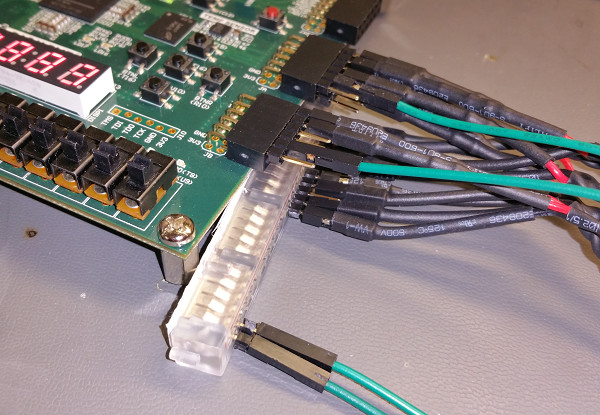
Once the code and driver were working correctly, the next step was adding Digital Discovery. The Digital Discovery has 40 I/O pins, and, as we already know, 24 of them are dedicated as digital inputs connected to the front 32-pin port. Two additional PMOD compatible ports are located on either side of the device and can be used for both input and output.

pic. 5 Three different pin header connectors allow for up to 40 digital signal connections.
A total of 11 pins were monitored, 1 for each segment and 1 for each cathode.

pic. 6 Connecting the Digital Discovery fly-wire harness to the CMOD A7 pins.
Once everything was connected, it was just a matter of recording the data using the WaveForms software.

pic. 7 The recorded data from the A7.

pic. 8 Zoomed data recorded from the A7 at about 6 Hz per count on the display.
The Digital Discovery defaults to 200 million samples per second (MS/s), but is capable of up to 800 MS/s, which would be far beyond the reach of the CMOD A7 board. A Nexys 4 board with a 100 Mhz clock was used for subsequent tests. In order to use the 800 MS/s option, a High-Speed Adapter was used, and High-Speed Probes, which enable fast-changing signals to be registered, were connected to the adapter. The HSPs were then connected to Digital Discovery through the HSA.

Pic. 9 HSPs connected to the HSA.
The display control signals were routed to two PMOD connectors of the Nexys 4 board. The probes were also attached to those connectors. The GND pins were tied together. The fact that the free ends of the probes were equipped with heat-shrink tubing, which gives strength to the connection, but also makes it difficult to place more than three wires next to each other on a standard bread-board with 100 mil spacing, had to be considered at this point. Therefore, there was a need to show some creativity with the connections.
pic. 10 Connecting the probes to the Nexys 4.
The code was then modified to work with the Nexys 4 board and then loaded. The ones digit on the 4-digit display was driven by the 100 MHz system clock. Therefore, the thousands digit was cycling between 0 and 9 at the frequency of 10 KHz. That is definitely too fast for the human eye to see.
By making a couple of adjustments to the Digital Discovery logic analyser settings?

pic. 11 Choosing the 800 MS/s option restricts the inputs to pins 0-7.

and recording the data?

pic. 12 The data recorded from the Nexys 4 running at 100 MHz.
?the digits became visible. In the above image, the part of data to the left of the first red cursor is the segment signal data while the thousands digit is turned on. Zooming in on the cursor we can see the following:

pic. 13 The division between segment data for the thousands digit and the ones digit.
project summary
We can clearly see (pic. 14) the segment signals coming through, represented by the decimal values at the top of the bus, highlighted in blue. These are the coded values for the 7-segment display. The binary value of 1111000 mapped to GFEDCBA segments (the low logic signal is active) informs us that segments A, B, and C are on, and the digit 7 is displayed. Looking at the rest of the decimal data, we can see that counting from 0 to 9 and resetting back to 0 is done within the span of 100 ?s!
A zoomed-in big white block of data (right side of pic. 14) is shown below. That's the data coming to the display upon selecting the ones digit, at a frequency of 100 MHz.
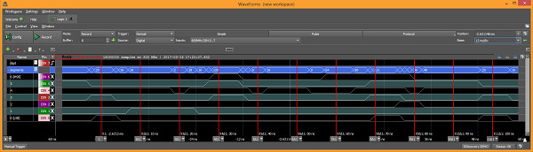
pic. 14 Segment data for idividual digit.
Several cursors were added to highlight the intervals. The cursors are all 10 ns apart, and when you look at the decimal value (displayed in blue at the top of each cursor), it matches the same sequence of data as the previous image. This time, counting from 0 to 9 and resetting back to 0 was done at 100 MHz. There were 8 data points between the cursors, therefore the state transitions were not precisely defined. It might seem like some abnormal data was recorded, however it should be noted that while the data on the blue line seems disrupted, several channels in that bus are simultaneously changing their states. It could also seem that these signals are not all changing at the same time.
However, something should be considered at this point? The copper traces on the Nexys 4 PCB connecting the FPGA to the PMOD output were not designed to send fast-changing signals. It means that at such speeds the physical distance between the connector and the FPGA has introduced an unavoidable signal propagation delay. This delay could be noticed in the recorded data (see above). The ability to see that is truly fascinating, especially on a device as small and compact as the Digital Discovery!
In conclusion, the Digital Discovery is perfect for applications requiring flexibility in setting logic level thresholds, fast communication speeds (such as transmitting video signals), or simultaneously analysing up to 32 digital channels. More information can be found at Transfer Multisort Elektronik's website (www.tme.eu).
Link to the e-shop with Digital Discovery
Link to the e-shop with Analog Discovery 2