

New version of Wi-Fi module (v1.1) for IoT platform called BigClown
- August 25 2019
- BigClown
- 26775 Reads
- 0 Comments

Wi-Fi module is used for Wi-Fi connection with your server and sending/receiving data with BigClown IoT platform. Wi-Fi connectivity is missing in the offer of BigClown.
If you use Wi-Fi module and Wi-Fi connectivity is enough for your project, you can use Core module without Radio and save 10 euros.
Core module controls ESP8266 by AT commands by UART.
Wi-Fi module for BigClown is available on tindie.com: https://www.tindie.com/products/chiptron/wi-fi-module-with-esp8266-for-bigclown-bare-pcb/
Github: https://github.com/petus/BigClown-Wi-Fi-module-v1.1
BigClown IoT platform: https://www.bigclown.com/ and also on https://time4ee.com/articles.php?cat_id=14
The one big advantage is connector for sensors - you can use TAG by BigClown or 4-pins, 5-pins sensor like Si7021, BME280, BMP180 and much more.
The pinout of sensor and TAG has to be:
VCC (or GND); GND (or VCC); SCL; SDA; INT.
The switching between VCC and GND on connector is choose by soldering bridges.
The pin header which you may use SMT (like BigClown) or THT. Both of them can be assembled.
This ESP8266 Wi-Fi module is supported by SDK of BigClown, so you just use existing functions.
What ESP8266 module may I use?
That's second advantage - you can use ESP07, ESP08, ESP12E of ESP12F. It is depending on you and your project.
How to start
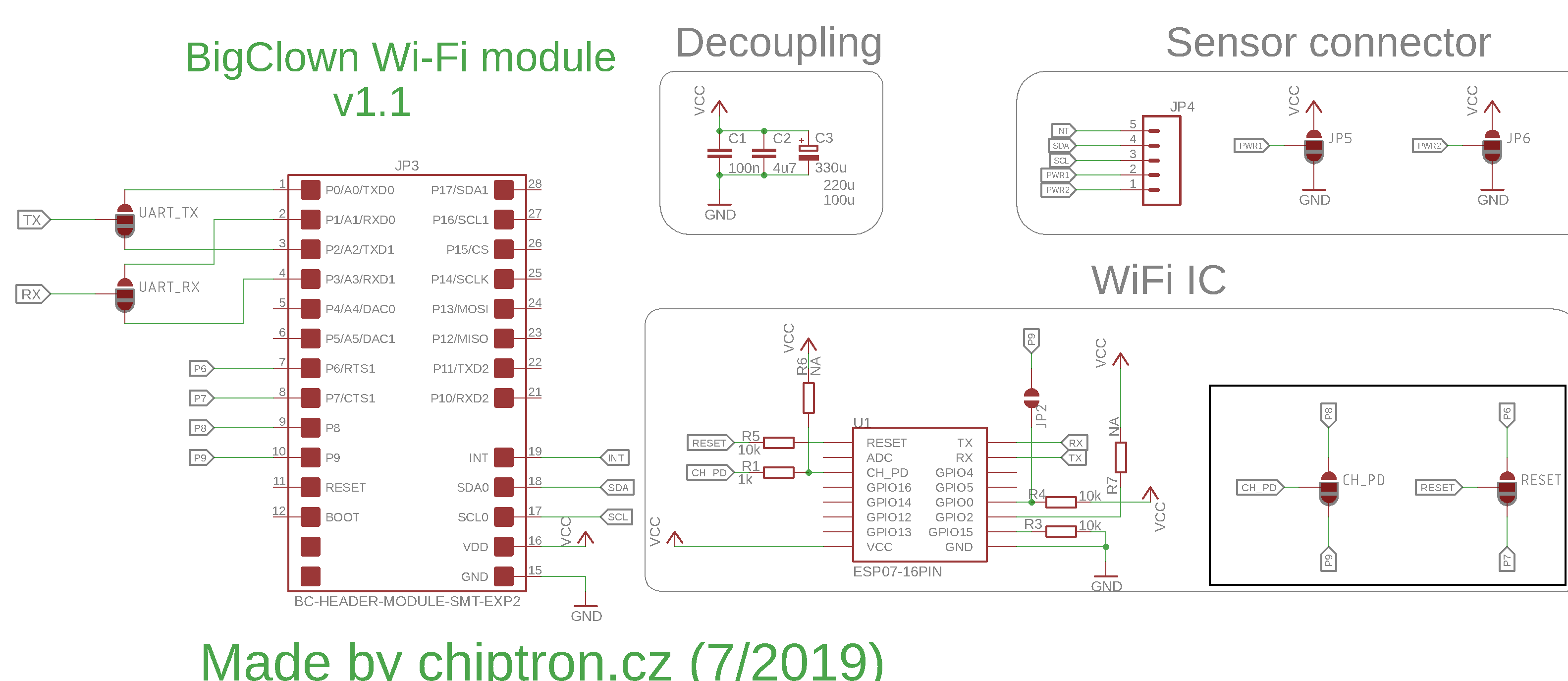
At first, you have to soldere four soldering bridges - UART TX, UART RX, CH PD, RESET.
UART TX - choose UART0 or UART1 which will be connected to RX of ESP8266.
UART RX - choose UART0 or UART1 which will be connected to TX of ESP8266.
CH PD - enabling of ESP8266 - GPIO P6 or P7.
RESET - reset of ESP8266 - GPIO P8 or P9.
There are three types of dimensions of decoupling capacitors. It's not need to solder all of them.
At lease, you should solder C1 (100nF/0805) and C3 (at least 100uF/D like this).
I2C connector
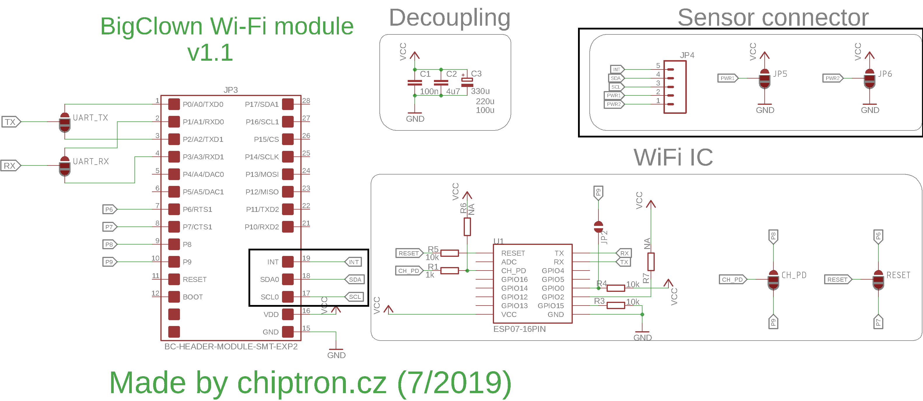
Wi-Fi module contains connector for connecting of Sensor. The design of connector is variable and you can modify the pinout of connector easily by soldering bridges.
PWR2 - choose VCC (3.3V) or GND on the first pin of connector
PWR1 - choose VCC (3.3V) or GND on the second pin of connector
Then SCL and SDA are connected to SCL0 (pin 17 and 18) and if the sensor includes INT pin, it is connected to INT of Core module (pin 19).
How to update the AT FW in ESP8266

In special cases, you have to update AT FW in ESP8266 module - for example using of SNTP or SSL.
It should be done by external USB-UART convertor with DTR and RESET output without connected Core module.
USB-UART convertor - Wi-Fi module
RX - RX[0,1] (pin P2 - UART0 or P4 - UART1); defined by soldering bridge UART_RX
TX - TX[0,1] (pin P1 - UART0 or P3 - UART1); defined by soldering bridge UART_TX
VCC - VCC (3.3V)
GND - GND
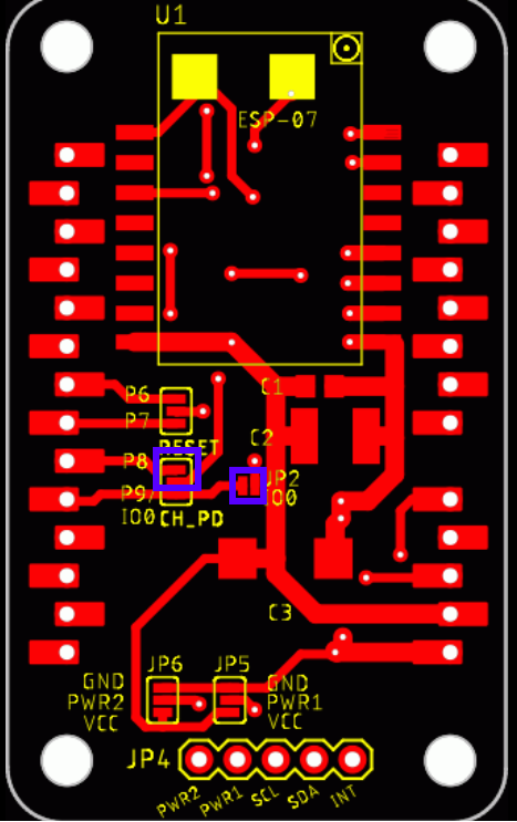
RST - CH_PD (pin P8 - short CH_PD solderbridge as is on picture bellow)
DTR - IO0 (pin P9, solder bridge JP2)
Then use Esptool for Linux OS or Windows.
More info is available on https://www.espressif.com/en/support/download/documents (ESP8266 Non-OS AT Instruction Set)
For my case, I used ESP8266 AT Bin V1.6.2 (8 Jun 2018) - available on https://www.espressif.com/en/support/download/at
The file contains (names may be different)
user1.1024.new.2.bin
esp_init_data_default_v08.bin
boot_v1.7.bin
blank.bin
I checked the README file and found there
# BOOT MODE
## download
### Flash size 16Mbit: 512KB+512KB
boot_v1.2+.bin 0x00000
user1.1024.new.2.bin 0x01000
esp_init_data_default.bin 0x1fc000 (optional)
blank.bin 0x7e000 & 0x1fe000
Plug in the external USB-UART convertor to USB (it is already connected to Wi-Fi module).
write this command (tried on Linux Mint)
/esptool-master $ sudo python esptool.py --port /dev/ttyUSB0 write_flash \
0x00000 ./bin/boot_v1.7.bin \
0x01000 ./bin/user1.1024.new.2.bin \
0x1fc000 ./bin/esp_init_data_default_v08.bin \
0x7e000 ./bin/blank.bin \
0x1fe000 ./bin/blank.bin
You should see in the terminal
esptool.py v2.8-dev
Serial port /dev/ttyUSB0
Connecting....
Detecting chip type... ESP8266
Chip is ESP8266EX
Features: WiFi
Crystal is 26MHz
MAC: 5c:cf:7f:e1:0f:e4
Uploading stub...
Running stub...
Stub running...
Configuring flash size...
Auto-detected Flash size: 2MB
Flash params set to 0x0030
Compressed 4080 bytes to 2936...
Wrote 4080 bytes (2936 compressed) at 0x00000000 in 0.3 seconds (effective 123.6 kbit/s)...
Hash of data verified.
Compressed 408388 bytes to 293527...
Wrote 408388 bytes (293527 compressed) at 0x00001000 in 25.9 seconds (effective 125.9 kbit/s)...
Hash of data verified.
Compressed 128 bytes to 75...
Wrote 128 bytes (75 compressed) at 0x001fc000 in 0.0 seconds (effective 85.2 kbit/s)...
Hash of data verified.
Compressed 4096 bytes to 26...
Wrote 4096 bytes (26 compressed) at 0x0007e000 in 0.0 seconds (effective 4679.1 kbit/s)...
Hash of data verified.
Compressed 4096 bytes to 26...
Wrote 4096 bytes (26 compressed) at 0x001fe000 in 0.0 seconds (effective 4675.9 kbit/s)...
Hash of data verified.
Leaving...
Hard resetting via RTS pin...
For testing, open the Serial console, set the baudrate - 115200 and write AT+GMR\r\n
AT version:1.6.2.0(Apr 13 2018 11:10:59)
SDK version:2.2.1(6ab97e9)
compile time:Jun 7 2018 19:34:26
Bin version(Wroom 02):1.6.2
OK
Working? Fine! That's all.
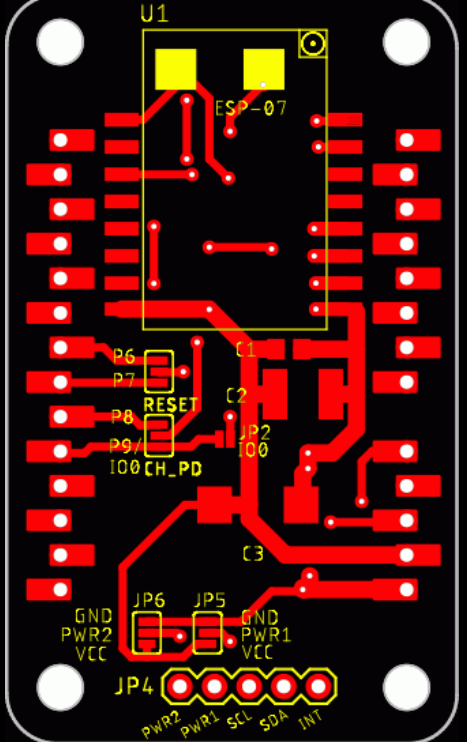
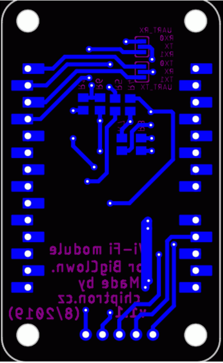
PCB
The PCB is two layers and components are from both sides.
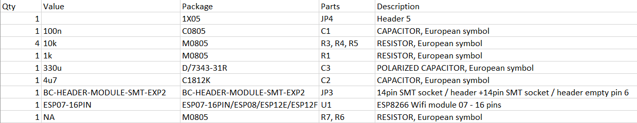
BOM
The headers can be used SMT or THT.
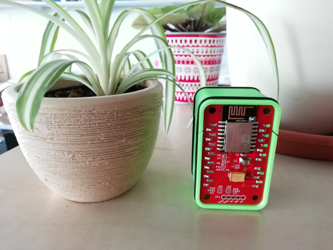
How does it look after soldering?
The ESP8266 is supported by BigClown SDK: https://github.com/bigclownlabs/bcf-sdk/blob/master/bcl/src/bc_esp8266.c
Example: https://github.com/bigclownprojects/bcf-wifi-cryptoclock
Wi-Fi module for BigClown is available on tindie.com: https://www.tindie.com/products/chiptron/wi-fi-module-with-esp8266-for-bigclown-bare-pcb/
Github: https://github.com/petus/BigClown-Wi-Fi-module-v1.1
BigClown IoT platform: https://www.bigclown.com/ and also on https://time4ee.com/articles.php?cat_id=14