About ESP32 and FireBeetle development board - I2S and Bluetooth
- November 09 2018
- ESP32, ESP8266, NodeMCU, Wemos ...
- 3715 Reads
- 0 Comments

I would like to thank Richard Štefún for this very good article about ESP32 and development board.
In previous article we introduced the ESP32 microcontroller and its peripherals. Now, we will focus on the practical use of one of its peripherals - Bluetooth.
Previous article: https://time4ee.com/articles.php?article_id=62
I decided to test this peripheral by constructing an A2DP audio receiver, which acts as a server that enables us to transfer audio signals from music player in my smartphone. Since it has been a recent trend to remove the audio jack from modern smartphones, this is a pretty practical design that I used for example in the older type of car radio and equipped it with the option of wireless audio transmission.
ESP32 supports communication with Bluetooth versions 4.2 BR / EDR and BLE. The manipulation of this peripheral under the Arduino IDE environment is very limited and I have decided to end up using the ESP-IDF environment. The toolchain can be downloaded and installed as described at https://esp-idf.readthedocs.io/en/latest/get-started/.
There are several examples in the examples folder, divided by the periphery. However, we are interested in the bluetooth folder in which the a2dp_sink project is located. If we manage to get this folder, we can invoke the configuration of the project by using the command "make menuconfig"
In the "Serial flasher config" configuration, we change the "Default serial port" to the Firebeetle communication serial port name. For me it was "/dev/tty.usbmodem1421" under Windows it should be the port named "COMx". We save the configuration by choosing "save", execute the command "make" and after compiling the software, we upload the code to board by calling the "make flash" command.
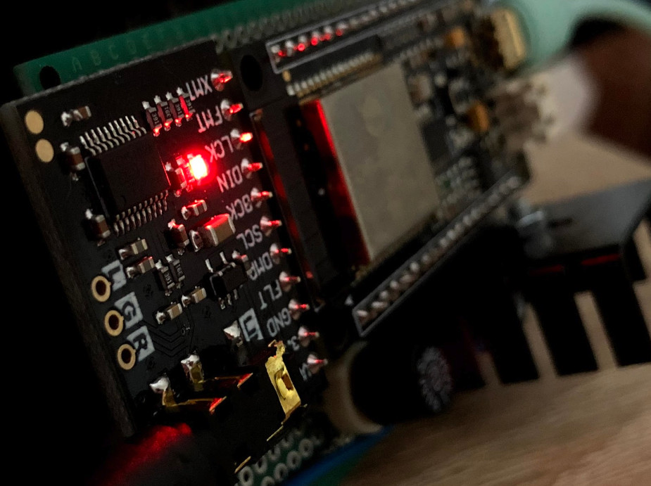
The software is preconfigured so that the output signal is generated using the I2S bus of the microcontroller. It is available with pins - 22 (LRCK), 26 (BCK), 25 (DATA). In my design, I decided to use the PCM5102A converter, which is fairly widespread, affordable and can be bought on development boards at a very affordable price.

Source of picture: https://www.aliexpress.com/item/PCM5102A-DAC-I2S-Interface-Decoder-Board-192KHz-24bit-3-5mm-Stereo-Jack-Digital-Audio-Player-Phat/32844562833.html
It is necessary to connect FLT, DMP, SCL and FMT contacts with GND and pin XMT with VCC (3.3V) to output an analogue signal. After searching for Bluetooth devices, select "ESP_SPEAKER". However, this name can be changed at any time after main.c and precompilation.
I soldered the development boards on perfboard with sockets and connected them using wire jumpers. I also added 5V voltage regulator, polarity protection and fuse.
The entire device is powered from the car radio output for the antenna amplifier. This output can be loaded up to 300mA, so at 150mA there is still a considerable margin within this range.
This design has been verified as fairly reliable, with only a few software bugs. The program does not handle buffer overflow when the signal is lost. If the smartphone accidentally disconnects from the device, noise can be heard from the output. The quality of the transmitted audio is excelet.


