

The board for weather station (meteostation) with ESP12E module (ESP8266, NodeMCU)
- August 11 2017
- ESP32, ESP8266, NodeMCU, Wemos ...
- 26038 Reads
- 0 Comments
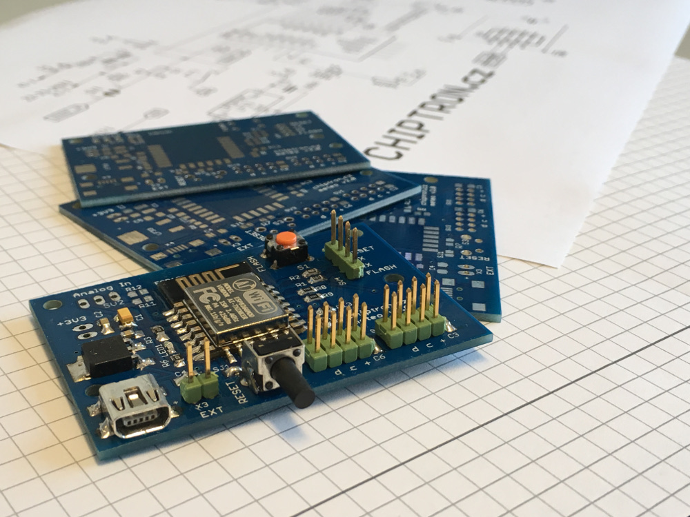
After my experiences with ESP12E (NodeMCU, ESP8266) and SHT75 temperature/humidity sensor I decided to make second version of board used for weather station. The first version is available on https://time4ee.com/articles.php?article_id=33.
The changes of previous board are not so important.
Do you like this project? Do you want the PCB? If you are from European Union, write me an e-mail on time4ee(AT)google(DOT)com.
The main component of board is ESP12E, the same WiFi modul with ESP8266 which uses NodeMCU development board.
The voltage regulator is LF33, LDO voltage regulator with 3.3V output voltage. The LDO regulates voltage from mini USB (5V) and from external power supply (up to 16V)- The input header for external power supply is labeled like EXT.
The board also contains 2pin header for connecting of 3.3V power supply.
The sensors are connected to board by 4x 4pin header with I2C bus.
4pin header is used for uploading of code. The USB-UART bridge is connected on these pins.
Connection, programming:
weather station board | USB-UART converter.
RESET -> DTR pin
TX -> RX
RX -> TX
FLASH -> GND
and power supply of course.
Arduino IDE
How to upload the code? Run Arduino IDE (or Sloeber IDE which is based on Eclipse IDE), choose NodeMCU board 1.0 version (if you don't have this board in list of boards, check this website).
Now, just click on Upload button. After uploading of code, disconnect USB-UART converter and the weather station works.
ESP8266 contains one analog input. So you can add some analog sensor. The board contains R11 a R12 resistors, these resistors can be used for decreasing of voltage.
If you want to use sleep down mode od ESP12E, solder SJ1 bridge(GPIO16 s RESET pinem).
User's LED is available on GPIO13.
The weather station board is kompatible with KM-27 plastic box.
Power consumption:
The power consumption during the sleep mode is 0.54mA (ESP12E + Si7021).
The connection of metestation board and I2C sensor.
weather station board | I2C sensor
+ -> VCC (3.3V)
c -> SCL (CLOCK)
d -> SDA (DATA)
pad without label -> GND
3D case.
The case for weather station board was designed for 3D printer. The source-codes are available on https://github.com/petus/ESP12E-Meteostation-v2.0/tree/master/3Dcase

OLED and weather station board
I added code for weather station board, temperature and humidity sensor Si7021 and OLED display 128x64px.
Values by sensor are showed on display.
How to connect the OLED to weather station board
I2C header of meteo board | OLED
c -> SCL (DO)
d -> SDA (D1)
+ -> VCC
GND -> pin without label
RESET pin of display connect to VCC (3.3V)
Link to code https://github.com/petus/ESP12E-Meteostation-v2.0/blob/master/ESP12E_meteo_v2.0_Si7021_OLED.ino

Radiation shield
I recommend the using of radiation shield. The measurement of temperature, humidity etc. is more accurate. You can mount the fan inside the shield. The fan ensures the airflow. So the data from sensors are more credible.

This project is available on github webpage https://github.com/petus/ESP12E-Meteostation-v2.0
Do you like this project? Do you want the PCB? If you are from European Union, write me an e-mail on time4ee(AT)google(DOT)com.
Thanks OK1RP.